In today’s interconnected world, the concept of a “smart home” has transitioned from a futuristic dream to a tangible reality. With the advancements in Internet of Things (IoT) technology, creating a smart home that adapts to your needs and enhances your lifestyle has become more accessible than ever. One of the popular platforms for building DIY IoT projects is the ESP32 microcontroller, coupled with the Blynk IoT platform. In this guide, we’ll delve into the world of ESP32 Blynk IoT home automation and explore how you can transform your living space into a smart oasis.
Understanding ESP32 and Blynk
Before we dive into the intricacies of home automation, let’s familiarize ourselves with the key components of our project: the ESP32 microcontroller and the Blynk IoT platform.
ESP32 Microcontroller
The ESP32 is a powerful yet affordable microcontroller that serves as the brains of our smart home system. It boasts built-in Wi-Fi and Bluetooth capabilities, making it ideal for IoT applications. With its dual-core processor and ample memory, the ESP32 can handle a wide range of tasks, from reading sensor data to controlling actuators.
Blynk IoT Platform
Blynk is a user-friendly IoT platform that allows you to control hardware remotely using a smartphone or tablet. With Blynk, you can create custom dashboards with buttons, sliders, and other widgets to interact with your IoT devices. It offers support for a variety of hardware platforms, including the ESP32, making it an excellent choice for DIY enthusiasts.
Setting Up Your Smart Home Environment
Now that we have a basic understanding of the tools at our disposal, let’s roll up our sleeves and start building our smart home.
1. Gathering Components
To get started, you’ll need the following components:


- ESP32 development board
- Jumper wires
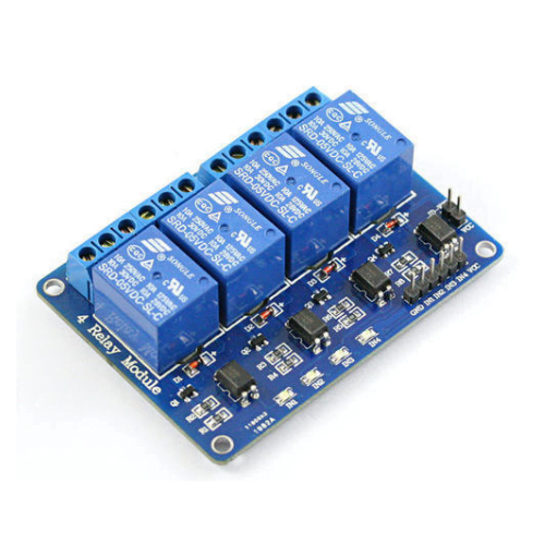
- 4-channel relay module
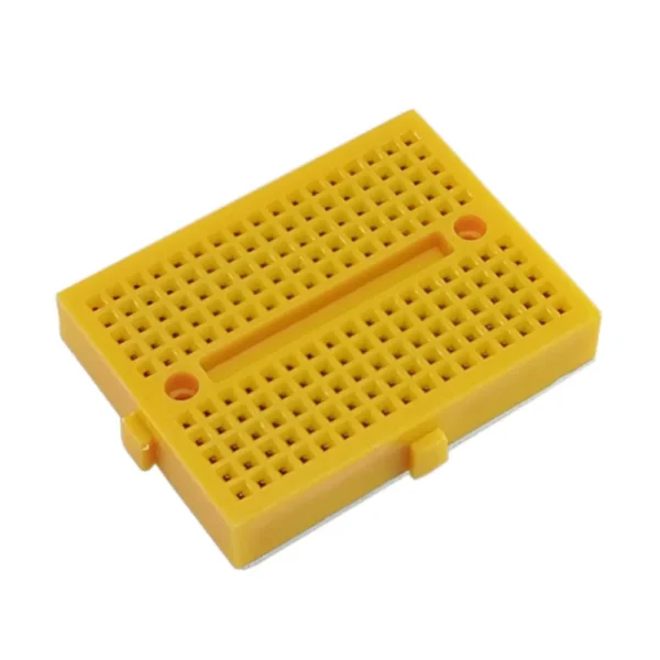
- Breadboard (optional, depending on your wiring preference)
- Power supply (make sure it’s compatible with your ESP32 and relay module)
2. Installing Blynk App
Download and install the Blynk app from the App Store or Google Play Store. Create a new account and log in to get started.
Open the Blynk app and create a new project. Choose the ESP32 as the hardware model and select the connection type Wi-Fi . You’ll receive an authentication token via email – make sure to keep it handy.
Writing ESP32 Code
1. Installing ESP32 Board Support
First, make sure you have the Arduino IDE installed on your computer. If not, download and install it from the Arduino website.
Next, add support for the ESP32 board to the Arduino IDE:
- Open the Arduino IDE.
- Go to File > Preferences (Arduino > Preferences on macOS).
- In the “Additional Board Manager URLs” field, add the following URL:
https://dl.espressif.com/dl/package_esp32_index.json - Click “OK” to close the Preferences window.
- Go to Tools > Board > Boards Manager.
- Search for “esp32” and install “ESP32 by Espressif Systems.”
- Once installation is complete, select your ESP32 board from Tools > Board.
2. Setting Up the Blynk Library
Ensure you have the Blynk library installed in your Arduino IDE:
- Go to Sketch > Include Library > Manage Libraries.
- Search for “Blynk” and install the “Blynk by Volodymyr Shymanskyy” library.
3. Writing and Uploading the Code
#define BLYNK_TEMPLATE_ID           "TMPL3W8e7ceaS"
#define BLYNK_TEMPLATE_NAME         "Quickstart Device"
#define BLYNK_AUTH_TOKEN            "YourAuthToken"

/* Comment this out to disable prints and save space */
#define BLYNK_PRINT Serial


#include <WiFi.h>
#include <WiFiClient.h>
#include <BlynkSimpleEsp32.h>

// Your WiFi credentials.
// Set password to "" for open networks.
char ssid[] = "YourWiFiSSID";
char pass[] = "YourWiFiPassword";


// Pin assignments for the relay module
#define RELAY_PIN_1  13 // Pin D13
#define RELAY_PIN_2  12 // Pin D12
#define RELAY_PIN_3  14 // Pin D14
#define RELAY_PIN_4 27 // Pin D27

// Initialize the Blynk connection
void setupBlynk() {
  Blynk.begin(BLYNK_AUTH_TOKEN, ssid, pass);
}

// Initialize the relay pins as outputs
void setupRelays() {
  pinMode(RELAY_PIN_1, OUTPUT);
  pinMode(RELAY_PIN_2, OUTPUT);
  pinMode(RELAY_PIN_3, OUTPUT);
  pinMode(RELAY_PIN_4, OUTPUT);

  digitalWrite(RELAY_PIN_1, 1);
  digitalWrite(RELAY_PIN_2, 1);
  digitalWrite(RELAY_PIN_3, 1);
  digitalWrite(RELAY_PIN_4, 1);
}

// Function to control relay states
void controlRelay(int relayNumber, bool state) {
  switch(relayNumber) {
    case 1:
      digitalWrite(RELAY_PIN_1, !state);
      break;
    case 2:
      digitalWrite(RELAY_PIN_2, !state);
      break;
    case 3:
      digitalWrite(RELAY_PIN_3, !state);
      break;
    case 4:
      digitalWrite(RELAY_PIN_4, !state);
      break;
    default:
      break;
  }
}

void setup() {
  // Initialize Serial Monitor
  Serial.begin(115200);

  // Connect to Wi-Fi
  WiFi.begin(ssid, pass);
  while (WiFi.status() != WL_CONNECTED) {
    delay(1000);
    Serial.println("Connecting to WiFi...");
  }

  // Setup Blynk
  setupBlynk();

  // Setup relay pins
  setupRelays();
}

// Function to handle Blynk button states
BLYNK_WRITE(V0) {
  int relayState = param.asInt();
  controlRelay(1, relayState);
}

BLYNK_WRITE(V1) {
  int relayState = param.asInt();
  controlRelay(2, relayState);
}

BLYNK_WRITE(V2) {
  int relayState = param.asInt();
  controlRelay(3, relayState);
}

BLYNK_WRITE(V3) {
  int relayState = param.asInt();
  controlRelay(4, relayState);
}

void loop() {
  Blynk.run();
}
Copy the provided code into a new sketch in the Arduino IDE.
- Replace the placeholders
ssid,pass, andBLYNK_AUTH_TOKENwith your Wi-Fi credentials and Blynk authentication token, respectively. - Verify and upload the sketch to your ESP32 board by clicking the “Upload” button.
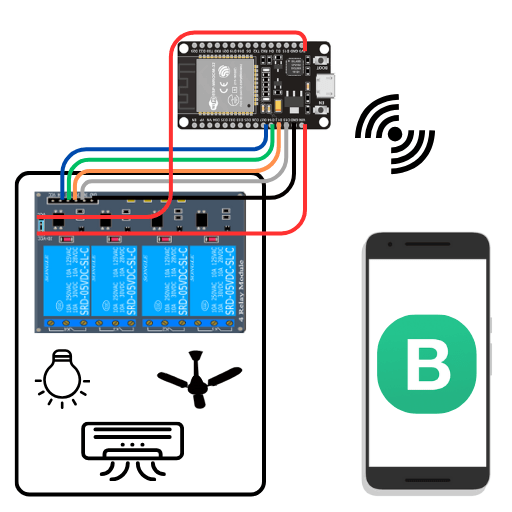
4. Connecting Hardware

Ensure your ESP32 board is connected to your computer via USB.
- Connect the VIN pin of the ESP32 to the JD-VCC pin of the relay module. This ensures that the relay module receives sufficient power from the ESP32.
- Connect the 3.3V pin of the ESP32 to the VCC pin of the relay module. This provides the required voltage for the relay module’s operation.
- Connect the relay module to the ESP32 using jumper wires. Refer to the pin assignments (
RELAY_PIN_1,RELAY_PIN_2,RELAY_PIN_3,RELAY_PIN_4) in the code and connect them accordingly.
5. Interacting with the Blynk App
Once uploaded, open the Blynk app on your smartphone or tablet.
- Load the project using the template ID and authentication token provided in the code.
- You should now be able to control the relay module from the Blynk app, toggling the states of the connected devices.
By following these steps, you’ll have successfully set up your ESP32 Blynk IoT home automation system, allowing you to control your devices remotely with ease.