Introduction:
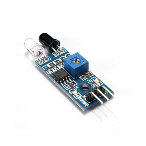
In this tutorial, we will learn how to interface an Infrared (IR) sensor with the ESP32 microcontroller. The IR sensor used in this tutorial consists of two IR LEDs and three pins, making it a simple and cost-effective choice for various applications like obstacle detection, proximity sensing, and remote control systems.
Components Needed:

- ESP32 development board
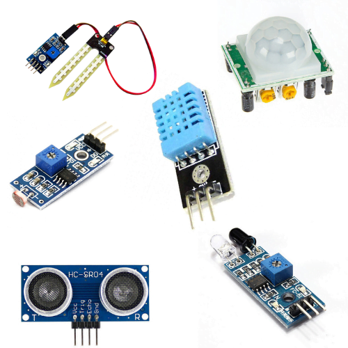
- IR sensor
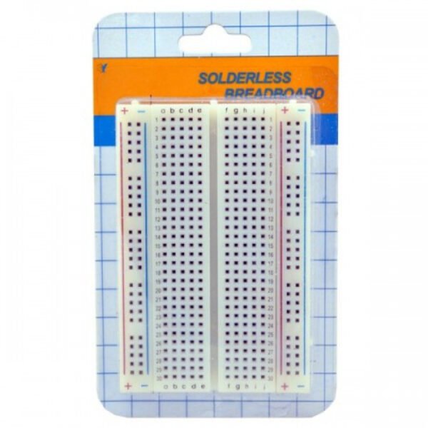
- Breadboard (optional)
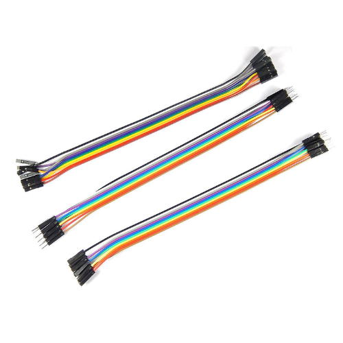
- jumper wires
- Power source (USB cable for ESP32)
Circuit Connection:
Connect the components as follows:
- Connect the VCC pin of the IR sensor to the 3.3V output on the ESP32.
- Connect the GND pin of the IR sensor to the GND pin on the ESP32.
- Connect the OUT pin of the IR sensor to a digital input pin on the ESP32, e.g., GPIO 2.
")
Note: Double-check the pin configurations of your specific IR sensor, as they may vary slightly between models.
Arduino IDE Setup:
Open the Arduino IDE on your computer.
Install the ESP32 board support:
- Go to File -> Preferences.
- Add the following URL to the “Additional Boards Manager URLs” field:
https://dl.espressif.com/dl/package_esp32_index.json. - Click OK.
- Go to Tools -> Board -> Boards Manager.
- Search for “esp32” and install the “esp32” board support.
Select the ESP32 board:
- Go to Tools -> Board and select your ESP32 board variant (e.g., ESP32 Dev Module).
Install the CH340G driver:
- download Windows CH340 Driver
Programming the ESP32:
// Define the IR sensor pin
#define IR_SENSOR_PIN 2

void setup() {
  // Start the Serial communication
  Serial.begin(115200);

  // Set the IR sensor pin as input
  pinMode(IR_SENSOR_PIN, INPUT);
}

void loop() {
  // Read the state of the IR sensor
  int irSensorState = digitalRead(IR_SENSOR_PIN);

  // Display the state on the Serial Monitor
  Serial.print("IR Sensor State: ");
  Serial.println(irSensorState);

  // Add your desired actions based on the IR sensor state
  // For example, you can trigger an action when the sensor detects an obstacle

  // Add a short delay to avoid rapid readings
  delay(500);
}
Explanation:
- Define Pins: The IR sensor pin is defined using
#define IR_SENSOR_PIN 2. Change this value if you connected the sensor to a different pin. - Setup Function: In the
setup()function, Serial communication is initiated, and the IR sensor pin is configured as an input. - Loop Function: The
loop()function continuously reads the state of the IR sensor usingdigitalRead(IR_SENSOR_PIN). The state is then printed to the Serial Monitor. - Add Actions: You can add your desired actions based on the IR sensor state. For instance, you might trigger a specific action when the sensor detects an obstacle.
- Delay: A short delay of 500 milliseconds is added at the end of the loop to prevent rapid readings.
Upload this code to your ESP32 board using the Arduino IDE and monitor the Serial Monitor to observe the IR sensor’s state changes.
Conclusion:
This simple tutorial demonstrates how to interface an IR sensor with an ESP32. You can further expand on this project by implementing specific actions based on the IR sensor’s state, making it suitable for various applications. Experiment with different scenarios and enhance the code to suit your project requirements.