Introduction:
In this tutorial, we will guide you through the process of building a simple yet effective laser security system using readily available components such as an ESP32 microcontroller, a laser module, a Light Dependent Resistor (LDR), and a buzzer. This system will detect unauthorized entry by sensing interruptions in the laser beam and trigger an alarm using the buzzer.
Materials Required:
- ESP32 development board
- Laser module
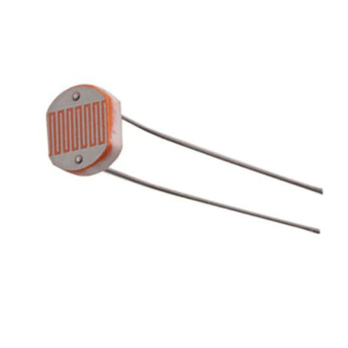
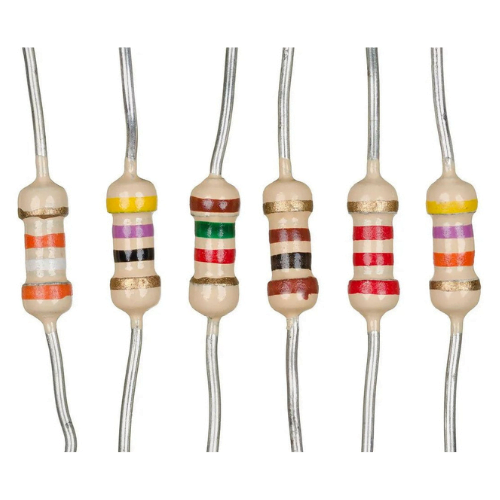
- Light Dependent Resistor (LDR)
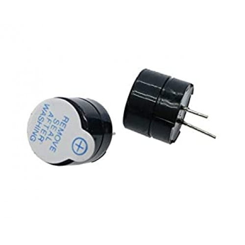
- Buzzer
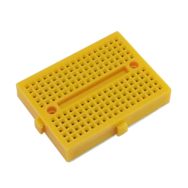
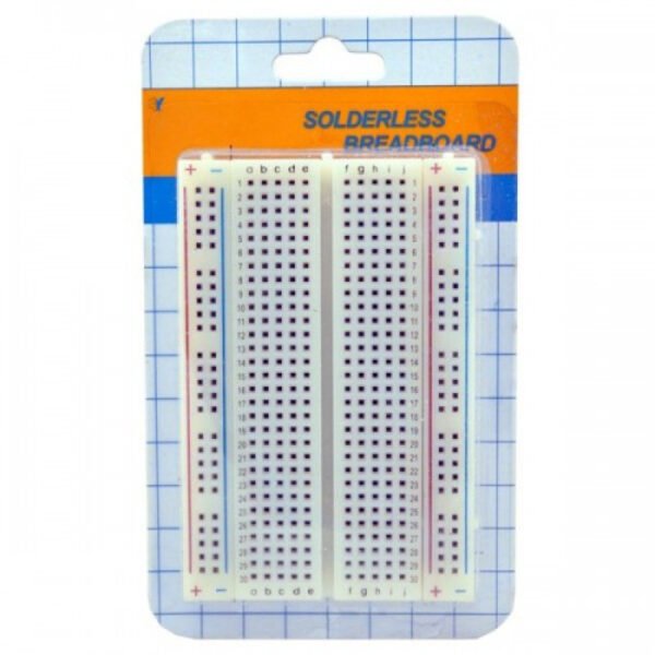
- Breadboard
- Jumper wires
- 10k Resistor
- Power source (USB cable or batteries)

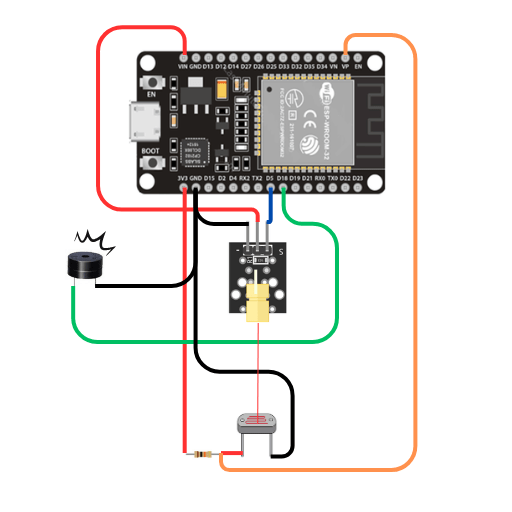
Connections:
- Connect the laser module’s control pin to any GPIO pin (e.g., D5) on the ESP32 development board.
- Connect the LDR
- Connect one end of the LDR to the analog pin on your ESP32 (e.g., A0 – VP).
- Connect the other end of the LDR to ground (GND).
- Connect one end of 10k resistor to the same point where the LDR is connected to the analog pin.
- Connect the other end of the resistor to the 3.3V power source.
- Connect + terminal of the buzzer to any digital pin (e.g., D18) on the ESP32.
- Connect the – terminal of the buzzer to the ground (GND) pin on the ESP32.
- Power up the ESP32 board using a USB cable or batteries.
Programming the ESP32:
Create a new sketch in Arduino IDE and copy-paste the following code:
const int laserPin = 5;   // Define the GPIO pin connected to the laser module
const int ldrPin = A0;    // Define the analog pin connected to the LDR
const int buzzerPin = 18;  // Define the digital pin connected to the buzzer

void setup() {
  pinMode(laserPin, OUTPUT);     // Set laser pin as output
  pinMode(buzzerPin, OUTPUT);    // Set buzzer pin as output
  pinMode(ldrPin, INPUT);    // Set buzzer pin as output

  digitalWrite(laserPin, HIGH);  // Turn on the laser initially
  Serial.begin(9600);            // Initialize serial communication
}

void loop() {
  int ldrValue = analogRead(ldrPin);  // Read LDR value
  Serial.println(ldrValue);           // Print LDR value for debugging

  if (ldrValue > 1500) {              // If laser beam is interrupted
    digitalWrite(buzzerPin, HIGH);    // Turn on the buzzer
    delay(1000);                      // Wait for 1 second
    digitalWrite(buzzerPin, LOW);     // Turn off the buzzer
  }
}
Before uploading the code to the ESP32, make sure to select the correct board (ESP32 Dev Module) and port from the Tools menu.
Testing:
Once the code is uploaded successfully, the system is ready for testing. Place the laser module and LDR facing each other, ensuring that the laser beam falls directly onto the LDR. Try interrupting the laser beam by placing an object between the laser module and the LDR. You should hear the buzzer sound when the laser beam is interrupted, indicating the detection of unauthorized entry.
Conclusion:
Congratulations! You have successfully built a DIY laser security system using ESP32, laser module, LDR, and buzzer. You can further enhance this system by integrating features such as notifications via Wi-Fi or SMS, and remote monitoring using a smartphone application. Experiment with different configurations and expand the functionality according to your requirements. Happy tinkering!